Cookie Consent by Free Privacy Policy website

Special application MA-LC MA-LCM


Download PDF

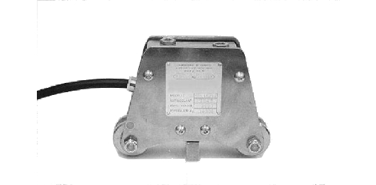
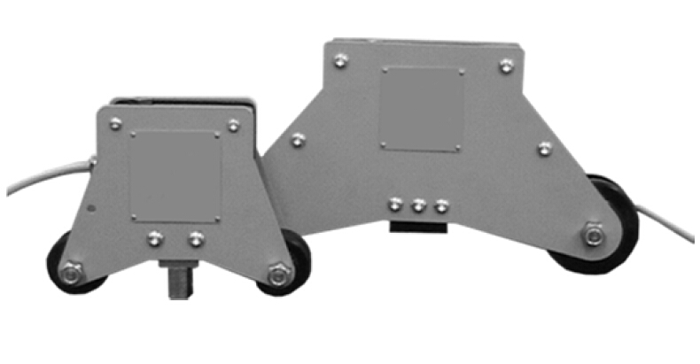
MECHANIC LOAD LIMITER

The load limiters of the MA-LC series are applied to the fixed rope with a simple operation.

The complete series covers a range of standard applications up to 10,000 kg pull on the rope with one or two intervention thresholds.

For different applications, models with more intervention thresholds and higher nominal loads are produced on specific request.

The basic models are powder coated and with galvanized parts, while for installation in outdoor environments or exposition to particularly corrosive agents, models are made entirely of stainless steel and with anti-explosive limit switches


  • Maximum electrical load: 250V - 15A
  • Mechanical life: 3,000,000 operating cycles
  • Insulation class (IP): IP 64 load limiter - IP 67 safety switches
  • Operating temperature: -20 ° to +50 °
  • Standard cable: 4m

Download installation and usage manual


Zoom Click to enlarge image

Special application MA-LC MA-LCM Special application MA-LC MA-LCM Montaggio
Analog Output

Technical Specifications

OutputOptional 0-10 V or 4-20 mA
Operating temperature-20 / +50°C (-4 / +122°F)
Protection classIP 64 – load limiter, IP 67 – safety end switch
Standard cable length4 m
For the complete and latest technical specifications, please refer to the technical data sheet which can be downloaded here:
Download PDF

MOUNTING OF THE LOAD CELL

General precautions to be followed in the installation and assembly of load cells:

  • Follow the direction of application of force on the load cell
  • Do not exceed the limits of the temperature as indicated in the data sheet
  • Do not remove labels from the load cell
  • Adequately protect the cables with sleeves or channels
  • Carry out on each load cell a ground connection with suitable cable, shunt on mounting accessories
  • Do not carry out any welding on the mechanical structure after mounting the load cell
  • Avoid or reduce to a minimum level any mechanical constraints between the rigid structure and the weighing structure to avoid error in weighing and return to zero
  • In case of vibration or dynamic loads product the load cells with puffers / shock absorbers
  • Protect load cell from any dust accumulation with any appropriate means