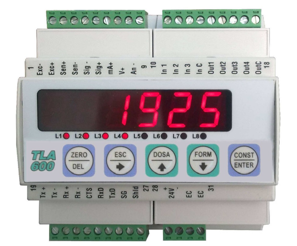
Weight indicator with 4 set points settable over the entire measuring range, logic outputs on four voltage free contacts (115Vac / 30Vdc, 0.5 A). For equal or greater weight values of setted set-point the contacts will be closed. The opening or closing of the contacts will take place taking into account the hysteresis values set in the constants. The instrument has 3 inputs with the following functions:
- Zero weight;
- Sending a string with the weighing data to a printer 24 column
- Net / gross weight or Peak function.
The calibration of the instrument can be done by setting constants parameters in the instrument setup or using a weight sample.
Download installation and usage manual ![]()
![]() Click to enlarge image
Click to enlarge image

| Power supply | 24 V dc ± 15 % | |
| Max power consumption | 5 W | |
| Isolation | Classe II | |
| Installation Category | Category II | |
| Operating temperature | -10 / +50 °C (14 / 122 °F) Humidity Maximum 85% non-condensing | |
| Storage temperature | -20 / +60°C (-4 / +140°F) | |
| Display | Numeric 8-digit, 7-segment LED (h 14 mm) | |
| Led | 8 3 mm indicator LEDs | |
| Keyboard | 5 membrane buttons | |
| Overall dimensions | 106 x 60 x 110 mm / 4.17 x 2.36 x 4.33 in (l x h x p) incluse morsettiere | |
| Mounting | DIN-rail (EN 60715) according to DIN 43880 | |
| Case material | Self-extinguishing PPO | |
| Connections | Removable screw terminal blocks, 5 mm pitch | |
| Power supply load cells | 5 V dc / 120 mA (maximum 8 cells with 350 Ω in parallel) protected against short-circuit | |
| Input sensitivity | ≥ 0,02 μV | |
| Linearity | < 0.01% of full scale | |
| Temperature deviation | <0,0003% of full scale/°C | |
| Internal resolution | 24 bit | |
| Weight resolution | Up to 99,999 divisions | |
| Measuring range | From -3.9 mV/V to +3.9 mV/V | |
| Digital filter | 0.2 Hz a 50 Hz | |
| Number of weight decimals | 0 to 4 decimal places | |
| Zero / FS Calibration | Automatic (theoretical) or executable through buttons | |
| Analog output in tension | Optional: 0-10 V / 0-5 V | |
| Resolution | 16 bits | |
| Calibration | By push-buttons | |
| Impedance | ≥ 10 kΩ | |
| Linearity | < 0.03% of full scale | |
| Temperature deviation | <0,001 % of full scale/ °C | |
| Analog output under current | Optional: 0-20 mA / 4-20 mA | |
| Resolution | 16 bits | |
| Calibration | By push-buttons | |
| Impedance | ≤ 300 Ω | |
| Linearity | < 0.03% of full scale | |
| Temperature deviation | < 0.001% of full scale / C° | |
| Logical output | 4 opto-relays (NO contact) maximum 24 V alternating current / 24 V direct current, 60 mA each | |
| Logical input | 3 opto-isolated at 12 / 24 V dc PNP | |
| Serial port | COM1: Rs232c half duplex COM2: Rs422/Rs485 half duplex. | |
| Max. cable length | 15m (Rs232c), 1000m (Rs422 e Rs485) | |
| Serial protocols | ASCII, Printer, EPSON, Modbus | |
| Baud rate | 1200, 2400, 4800, 9600, 19200, 38400, 115200 | |
| Program code memory | 60 Kbytes FLASH reprogrammable onboard RS232 | |
| Data memory | 4 Kbytes | |
| Conforms to standards | EN61000-6-2, EN61000-6-3, EN61010-1, EN45501 | |
| Type | TLA terminal block (upper) |
| Length | ND |
| 1 | Load cell power supply - |
| 2 | Load cell power supply + |
| 3 | Load cell ref + |
| 4 | Load cell ref - |
| 5 | Load cell signal - |
| 6 | Load cell signal + |
| 7 | + Analog current output |
| 8 | + Analog voltage output |
| 9 | - Analog output |
| 10 | Input 1 |
| 11 | Input 2 |
| 12 | Input 3 |
| 13 | Common input |
| 14 | Output 1 |
| 15 | Output 2 |
| 16 | Output 3 |
| 17 | Output 4 |
| 18 | Common Outputs |
| Type | TLA terminal block (lower) |
| Length | ND |
| 19 | TX+ RS 422 |
| 20 | TX- RS 422 |
| 21 | RX+ RS 422 |
| 22 | RX- RS 422 |
| 23 | CTS |
| 24 | RX RS 232 |
| 25 | TX RS 232 |
| 26 | SGND |
| 27 | Shield serial cables |
| 28 | + 24 Vcc |
| 29 | GND |
| 30 | NC |
| 31 | NC |
General precautions to be followed in the installation and assembly of load cells: