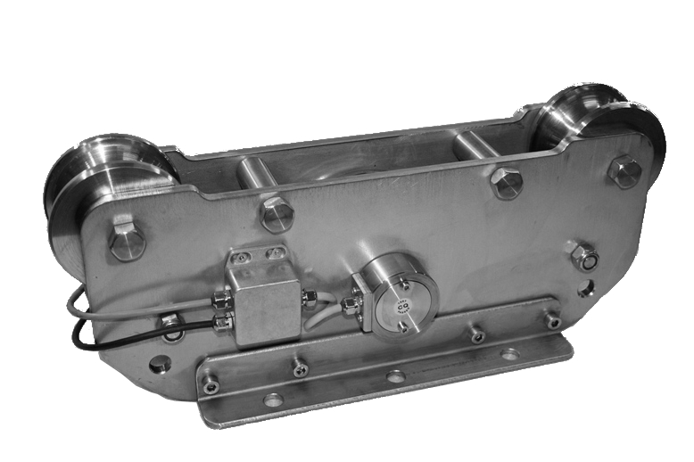
TR.DI.CO is the sliding tension rope, with overload limiter function, "Made in Europe" design and production, CE marked. Ideal for installation of hoists and winches, both new and already in operation , as the simple steps of installation does not require the interruption of the rope.
As the Nordic giant from which it takes its name, TR.DI.CO is strong, sturdy, specially designed to work in the most extreme environments. The compact and accurate design and high reliability make this an incomparable tool for tension control and the safety of the installations of the rope pulling. The standard range of TR.DI.CO models covers a capacity range between 0 and 500 tons ropes with diameters up to 120 mm.
The structure of TR.DI.CO all parts are made of stainless steel. The tension of the rope is measured by a load cell pin stainless steel with high elastic properties.
| Model | Weight | Max Tension | Max rope dim. |
Dimensions (cm) |
| TR.DI.CO 5K |
7 kg | 5.000 daN | 20 mm | 28x18x18(h) |
| TR.DI.CO 25K |
15 kg | 25.000 daN | 40 mm | 48x16x18,5(h) |
| TR.DI.CO 50K |
50 kg | 50.000 daN | 50 mm | 48x25x38(h) |
Pin load cell: CE Certified, upon request ATEX or IECEx certification
![]() Click to enlarge image
Click to enlarge image


| Material | Stainless steel |
| Nominal load | 5, 25, 50 t |
| Limit load | 150 % F.S. |
| Breaking load | 300 % F.S. |
| Supply voltage | Max. 15 V dc (option 24 V cd) |
| Output | 1 mV/V (option 4-20 mA) |
| Output tollerance | 0,1 % F.S. |
| Zero tollerance | 1 % F.S. |
| Linearity | 0,2 % F.S. |
| Hysteresis | 0,2 % F.S. |
| Reapeatability | 0,2 % F.S. |
| Input resistance | 350-360 ohm |
| Output resistance | 350-353 ohm |
| Insulation resistance | >= 2000 Mohm |
| Creep (30 Minutes) | 0,2 % F.S. |
| Thermal compensation | -10 / +40°C (14 / +104°F) |
| Operating temperature | -20 / +70°C (-4 / +158°F) |
| Temperature deviation zero | 0,003 % F.S. / °C |
| Temperature deviation full scale | 0,002 % F.S. / °C |
| Protection class | IP 67 |
| Standard cable length | 5 m – 4 x 0,25 (shield not connected to the load cell body) |
| Type | Standard electric cable (4x0,25) |
| Length | 5 m (body lead cell not connected shield) |
| Red | + REF |
| Black | - REF |
| Green | + OUT |
| White | - OUT |
General precautions to be followed in the installation and assembly of load cells: