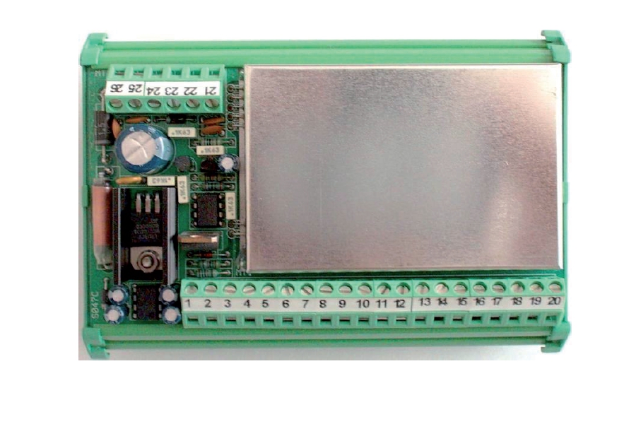
Weight Transmitters with direct connection of one ore more load cells and a wide range of outputs for an easy integration in every industrial and automation system. Comfortable and immediate installation on DIN bar and/or OMEGA bar.
Transmitter
![]() Click to enlarge image
Click to enlarge image

| Power supply | 24 V dc ± 15 % | |
| Max power consumption | 6 W | |
| Isolation | Class III | |
| Operating temperature | -10 / +40°C (14 °F / 104°F) Humidity maximum 85% non-condensing | |
| Storage temperature | -20 / +60°C (-4 / +140°F) | |
| Overall dimensions | 130 x 90 x 72 mm / 5.12 x 3.54 x 2.83 in (l x h x p) | |
| Mounting | Support DIN or OMEGA rail | |
| Case material | Polyamide 6.6 UL 94V-0, self-extinguishing | |
| Connections | Removable screw terminals. Pitch screws terminal blocks 5.08 mm | |
| Power supply load cells | 10 V dc / 120 mA (maximum 4 cells with 350 Ω in parallel) short circuit protection | |
| Linearity | 0,02 % of full scale | |
| Temperature deviation | 0,005 % of full scale/°C | |
| Measuring range | -0.5 / +3 mV/V | |
| Zero / FS Calibration | Adjustment zero and f. s. coarse by of micro switches 16 combinations, fine with 18-turn resistive trimmer | |
| Analog integrator filter | Adjustable w. single-turn trimmer | |
| Analog output in tension | 0 – 10 V / ± 5 V | |
| Impedance | ≥ 10 kΩ | |
| Analog output under current | 0 - 20 mA / 4 - 20 mA | |
| Impedance | ≤ 300 Ω | |
| Conforms to standards | Compliance to EMC norms: EN61000-6-2, EN61000-6-3, Compliance electric safety: EN 61010-1 | |
| Type | Terminal block MA 20P pitch 5.08 |
| Length | ND |
| 1 | Load cell 1, Exc. - |
| 2 | Load cell 1, Exc. + |
| 3 | Load cell 1, signal - |
| 4 | Load cell 1, signal + |
| 5 | Shield |
| 6 | Load cell 2, Exc. - |
| 7 | Load Cell 2, Exc. + |
| 8 | Load Cell 2, signal - |
| 9 | Load cell 2, signal + |
| 10 | Shield |
| 11 | Load cell 3, Exc. - |
| 12 | Load cell 3, Exc. + |
| 13 | Load cell 3, signal - |
| 14 | Load cell 3, signal + |
| 15 | Shield |
| 16 | Load cell 4, Exc. - |
| 17 | Load cell 4, Exc. + |
| 18 | Load cell 4, signal - |
| 19 | Load cell 4, signal + |
| 20 | Shield |
| Type | Terminal block MB 6P pitch 5.08 |
| Length | ND |
| 21 | Current analog out 0-20mA/4-20mA |
| 22 | Voltage analog out 0-10Vcc |
| 23 | Analog out (voltage / current) |
| 24 | - 24 vcc ± 15% |
| 25 | + 24 vcc ± 15% |
| 26 | Ground |
General precautions to be followed in the installation and assembly of load cells: