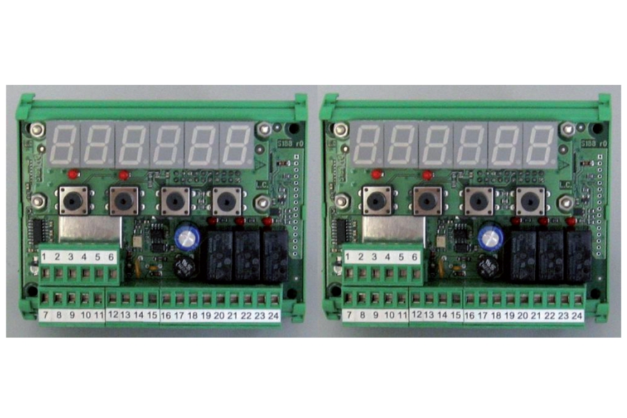
LOAD LIMITER
Limitation of the detected load through alarm and pre-alarm levels.
Overload control with double-security system by connecting two units.
Limitation of load (single and sum) for weighing systems up to 4 points, by connecting more units.
Load cell fail alarm and Set-up and calibration via keyboard and display board removable.
![]() Click to enlarge image
Click to enlarge image


| Power supply | 12 – 24 V ac ± 15 % | |
| Average consumption | 4 W | |
| Isolation | Class II | |
| Operating temperature | -10 / +50 °C (14 / 122 °F) Humidity Maximum 85% non-condensing | |
| Storage temperature | -20 / +60°C (-4 / +140°F) | |
| Display | Numeric 6-digit, 7-segment LED (h 14mm) | |
| Led | 5 3 mm indicator LEDs of which 3 indicate the relay outputs status | |
| Keyboard | 4 mechanical keys | |
| Overall dimensions | 115 mm x 93 mm x 65 mm / 4.53 x 3.66 x 2.56 in (l x h x p) | |
| Mounting | Support for DIN rail or OMEGA bar | |
| Case material | Polyamide 6.6 UL 94V-0, self-extinguishing | |
| Connections | Removable screw terminals. Pitch screws terminal blocks 5.08 mm | |
| Load cell input features | Max 4 | |
| Input sensitivity | ≥ 0,02 μV | |
| Linearity | < 0.01% of full scale | |
| Temperature deviation | < 0.001% of full scale/C° | |
| Internal resolution | 24 bit | |
| Measuring range | -3.9 mV/V - +3.9 mV/V | |
| Digital filter | 0.1 Hz – 10 Hz, selectable | |
| Output rate | 10 Hz | |
| Number of weight decimals | From 0 to 3 decimals | |
| Zero / FS Calibration | Executable through buttons | |
| Cell cable interruption check | Always present | |
| Analog output in tension | Optional: ± 10 V / ± 5 V | |
| Resolution | 16 bits | |
| Calibration | Digital through buttons | |
| Impedance | ≥ 10 kΩ | |
| Analog output under current | Optional: 0 - 20 mA / 4 - 20 mA | |
| Resolution | 16 bits | |
| Calibration | Digital through buttons | |
| Impedance | ≤ 300 Ω | |
| Logical input | 1 optically isolated dry contact | |
| Logical output alarm | 2 relay out (24 V DC/AC, one NO contact), 1 relay out (24 V DC/AC, one changeover contact), relay contact capacity 0.5 A | |
| Serial port | Rs232 / Rs485 (alternative) | |
| Max. cable length | 15m (Rs232) and 1000m (Rs485) | |
| Baud rate | Up to 115 kb/s (default 9600 b/s) | |
| Program code memory | 32 Kbytes | |
| Data memory | 2 Kbytes | |
| Conforms to standards | Compliance to EMC norms: EN61000-6-2, EN61000-6-3, Compliance electric safety: EN 61010-1 | |
| Type | 6 Pin pull-out terminal block |
| Length | ND |
| 1 | - Exc. Load cell |
| 2 | + Exc. Load cell |
| 3 | + Load cell Sense |
| 4 | - Load cell Sense |
| 5 | - Signal load cell |
| 6 | + signal load cell |
| Type | 18 Pin pull-out terminal block |
| Length | ND |
| 7 | RS232 Tx |
| 8 | RS232 Rx |
| 9 | RS232 GND |
| 10 | RS485 + |
| 11 | RS485 - |
| 12 | Input (Dry contact) |
| 13 | Input (Dry contact) |
| 14 | + ~ (Power supply 12 to 24 Vdc/Vac +/- 15%) |
| 15 | - ~ (Power supply 12 to 24 Vdc/Vac +/- 15%) |
| 16 | Analog output + (V or mA) |
| 17 | Analog output - |
| 18 | Common Relay Output 1 |
| 19 | N.O. contact Relay Output 1 |
| 20 | Common Relay Output 2 |
| 21 | N.O. contact Relay Output 2 |
| 22 | Common Relay Output 3 |
| 23 | N.O. contact Relay Output 3 |
| 24 | N.C. contact Relay Output 3 |
General precautions to be followed in the installation and assembly of load cells: