
Compression load cell TOR36
Download PDF datasheet
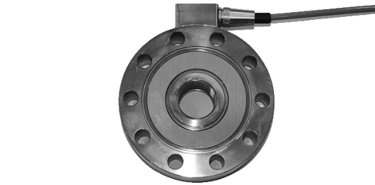
Compression load cells for weighing platforms, silos, hoppers etc..
Compression load cell TOR36
Upon request with ATEX or IECEx certification
Click on the image to enlarge
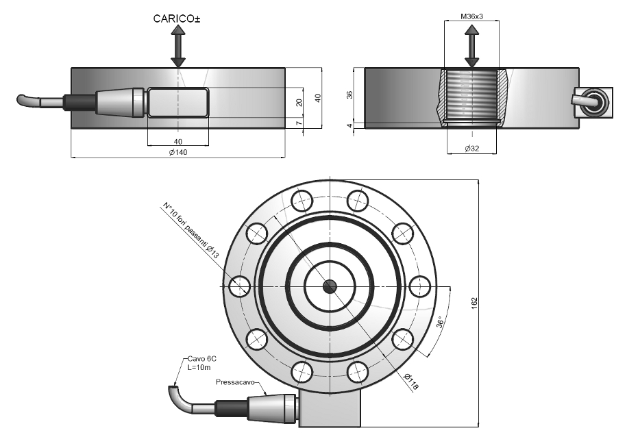


Technical specifications
| Material | Stainless steel |
|---|---|
| Nominal load | 4, 5, 7.5, 10, 12.5, 15, 20, 25, 30 t |
| Limit load | 150 % F.S. |
| Breaking load | 300 % F.S. |
| Supply voltage | Vcc 15 Max |
| Output | 2 mV/V |
| Output tollerance | 0,1 % F.S. |
| Zero tollerance | 1 % F.S. |
| Linearity | 0,03 % F.S. |
| Hysteresis | 0,03 % F.S. |
| Reapeatability | 0,03 % F.S. |
| Input resistance | 350-360 ohm |
| Output resistance | 350-355 ohm |
| Insulation resistance | >=2000 Ohm |
| Creep (30 Minutes) | 0,03 % F.S. |
| Thermal compensation | -10 / +40°C (14 / +104°F) |
| Operating temperature | -20 / +70°C (-4 / +158°F) |
| Temperature deviation zero | 0,003 % F.S. / °C |
| Temperature deviation full scale | 0,002 % F.S. / °C |
| Protection class | IP 68 |
| Standard cable length | 10 m – 6 x 0,35 (shield not connected to the load cell body) |
For complete and up-to-date technical specifications please refer to the datasheet you can download here
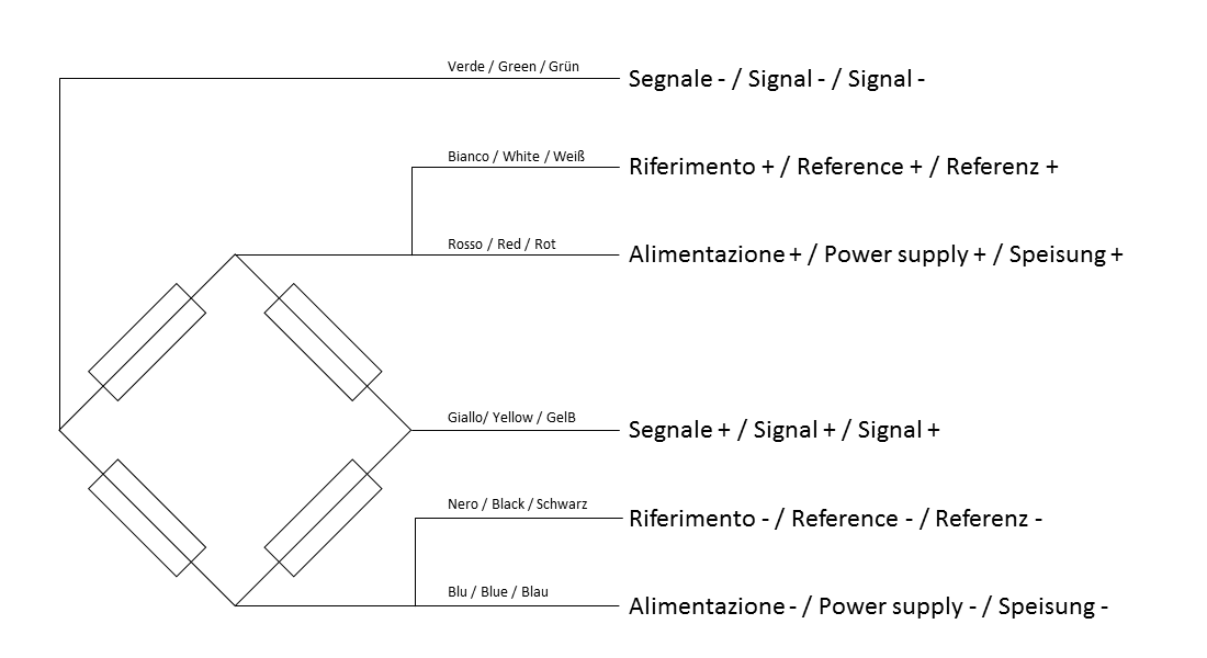
Download PDF datasheet Connections
| Type | SHIELDED CABLE 6C R7 PUR 6X0,35 |
|---|---|
| Length | 10 m (shield not connected to the cell body) |
| Red | + IN |
| Blue | - IN |
| White | + REF |
| Black | - REF |
| Yellow | + OUT |
| Green | - OUT |
Load cell mounting
General guidelines for installing and mounting load cells:
- Respect the direction in which forces are applied to the load cells
- Do not exceed the temperature limits shown on the rating plate
- Do not remove the labels from the cells
- Protect cables properly with sheaths or cable ducts
- Connect each cell to earth with a suitable cable, bridging the plates of the mounting accessories if necessary
- Do not weld on the mechanical structure once the cells are in place
- Avoid or minimise mechanical constraints between the fixed structure and the weighed structure, to prevent weighing errors and zero return problems
- When vibrations or dynamic loads are present, protect the cells with anti-vibration mounts
- Protect the cells from dust build-up with suitable covers