
Special application GR01
Download PDF datasheet
Gicam special applications: tension meters and load limiters for winch and hoist ropes, load pins and linear potentiometers for presses.
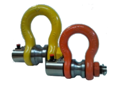
PIN LOAD CELL
Click on the image to enlarge
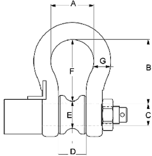


Technical specifications
| Material | Stainless steel |
|---|---|
| Nominal load | 1 – 100 t |
| Limit load | 150 % F.S. |
| Breaking load | 300 % F.S. |
| Supply voltage | Maximum 15 V dc |
| Output | 1 mV/V |
| Output tollerance | 0,1 % F.S. |
| Zero tollerance | 1 % F.S. |
| Linearity | 0,2 % F.S. |
| Hysteresis | 0,2 % F.S. |
| Reapeatability | 0,2 % F.S. |
| Input resistance | 350-360 ohm |
| Output resistance | 350-353 ohm |
| Insulation resistance | >= 2000 MOhm |
| Creep (30 Minutes) | 0,2 % F.S. |
| Thermal compensation | -10 / +40°C (14 / +104°F) |
| Operating temperature | -20 / +70°C (-4 / +158°F) |
| Temperature deviation zero | 0,003 % F.S. / °C |
| Temperature deviation full scale | 0,002 % F.S. / °C |
| Protection class | IP 67 |
| Standard cable length | 5 m – 4 x 0,25 (shield not connected to the load cell body) |
For complete and up-to-date technical specifications please refer to the datasheet you can download here
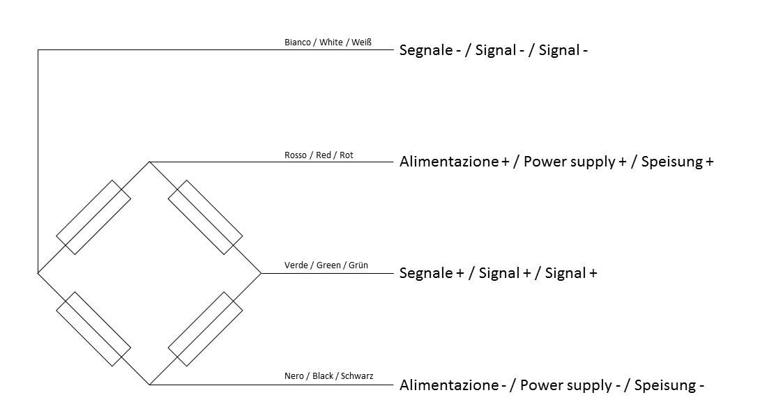
Download PDF datasheet Connections
Load cell mounting
General guidelines for installing and mounting load cells:
- Respect the direction in which forces are applied to the load cells
- Do not exceed the temperature limits shown on the rating plate
- Do not remove the labels from the cells
- Protect cables properly with sheaths or cable ducts
- Connect each cell to earth with a suitable cable, bridging the plates of the mounting accessories if necessary
- Do not weld on the mechanical structure once the cells are in place
- Avoid or minimise mechanical constraints between the fixed structure and the weighed structure, to prevent weighing errors and zero return problems
- When vibrations or dynamic loads are present, protect the cells with anti-vibration mounts
- Protect the cells from dust build-up with suitable covers