
Indicator RIN1-PL SIL2
Download PDF datasheet
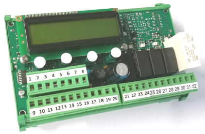
RIN1-PL is a load limiting system for dual channel connection for load cells. The cell must be double bridged in the case of systems where Performance Level PL d is required.
In the SIL 2 compliant version, in accordance with category 2 according to EN 13849-1: 2016, PL d (corresponding to SIL 2, EN62061 standard), the load limitation is implemented by means of relays, of which the BLOCK is a safety relay with guided contacts, monitored in real time, according to the EN50205 standard.
Click on the image to enlarge

Technical specifications
| Power supply | 20 - 50 VAC/VDC |
|---|---|
| Max power consumption | 6 VA |
| Isolation | Class III |
| Operating temperature | -10 °C / +50 °C |
| Storage temperature | -20 °C / +60 °C |
| Display | Backlit LCD, 2 lines of 16 characters, character height 5 mm |
| Logical output | Safety relay with guided contacts (EN50205), one changeover contact |
| Logical input | 2 optoisolated logic inputs (12/24 VDC) PNP |
| Additional logic outputs | No. 2 relays with one changeover contact |
| Logical output alarm | Relay with changeover contact |
| Conforms to standards | EN6100-6-2, EN6100-6-3 for EMC, EN61010-1 for electrical safety, EN13849-1 safety-related parts of control systems |
For complete and up-to-date technical specifications please refer to the datasheet you can download here
Download PDF datasheet Load cell mounting
General guidelines for installing and mounting load cells:
- Respect the direction in which forces are applied to the load cells
- Do not exceed the temperature limits shown on the rating plate
- Do not remove the labels from the cells
- Protect cables properly with sheaths or cable ducts
- Connect each cell to earth with a suitable cable, bridging the plates of the mounting accessories if necessary
- Do not weld on the mechanical structure once the cells are in place
- Avoid or minimise mechanical constraints between the fixed structure and the weighed structure, to prevent weighing errors and zero return problems
- When vibrations or dynamic loads are present, protect the cells with anti-vibration mounts
- Protect the cells from dust build-up with suitable covers